
MADE IN USA  Carbide Tipped & Solid Carbide Cutting Tools — manufacturing since 1986
Mon–Fri 7:00am–5:30pm CDT · (800) 345-8924
0%

Choosing the right Straight Shank Counterbores in 2026 requires more than comparing prices or browsing attractive product photos. The correct tool must match the fastener, material, machine, and required hole finish. A counterbore used on aluminum behaves differently from one cutting hardened steel. Small differences matter.

Experienced machinists usually inspect shank diameter, cutting geometry, pilot size, flute design, and coating options. These details influence stability, chip evacuation, surface quality, and tool life. A rigid straight shank can reduce runout when the chuck holds it securely. However, even a premium tool may perform poorly with incorrect speeds, feeds, or insufficient workholding.

Machine compatibility matters. So does operator judgment. Check the manufacturer’s dimensional data, recommended cutting conditions, material grades, and tolerance information before purchasing. Independent testing, verified reviews, and traceable quality records offer stronger evidence than vague marketing claims. Some suppliers provide impressive specifications but limited application guidance. That should encourage careful questioning.

This guide examines how to evaluate Straight Shank Counterbores for modern workshops, maintenance teams, and production environments. It considers tool materials, pilot selection, coating performance, accuracy, safety, and long-term value. Real-world conditions are rarely perfect. Machines vibrate, materials vary, and published tool life may not match every workshop. That is why selection should include trial cuts, measurement, and honest review of results. A reliable decision comes from evidence, not assumptions.
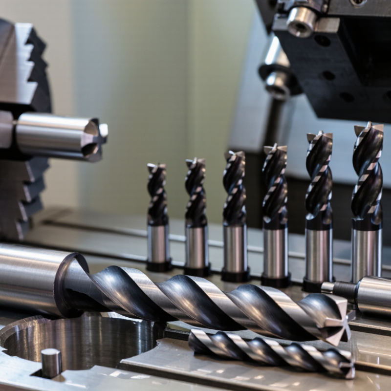
How to Choose Straight Shank Counterbores in 2026?

What Are Straight Shank Counterbores and How Do They Work?

How to Choose Straight Shank Counterbores in 2026?

A straight shank counterbore cuts a flat-bottomed recess around an existing hole. This recess lets a socket-head screw sit below, or nearly level with, the workpiece surface. Its straight cylindrical shank fits a drill chuck, collet, or milling holder. During cutting, the pilot enters the clearance hole and keeps the larger cutter centered. The cutting edges then remove material from the surrounding face. Simple in theory. Setup errors still matter.

Choose the counterbore from the fastener, not only the recess diameter. ISO 4762 defines common socket-head screw dimensions, while ISO 273 guides clearance-hole sizing. Match the pilot diameter to the hole with minimal looseness. Select a cutting diameter slightly above the screw-head diameter, and confirm the required recess depth. For steel, rigid clamping and moderate feed reduce chatter. Aluminum may need sharper geometry and chip clearance. In practical shop work, a loose pilot often creates a visibly uneven shoulder.

Grand View Research estimated the global cutting-tools market at about USD 21.55 billion in 2023, with continued growth through 2030. That expansion reflects wider machining demand, but it does not guarantee better tool selection. Tool life depends on material, spindle stability, coating, coolant, and operator judgment. I still verify the actual screw head with calipers. Catalog dimensions can be rounded. A small mistake becomes obvious when the fastener sits proud. For production work, record diameter, depth, spindle speed, feed, and measured tool wear after the first parts.

How to Choose Straight Shank Counterbores in 2026?

What Are Straight Shank Counterbores and How Do They Work?

A straight shank counterbore is a cylindrical cutting tool used to create a flat-bottom recess for seating socket-head cap screws below or flush with a workpiece surface. Select the tool by matching the screw size, required counterbore diameter, cutting depth, shank diameter, workpiece material, and machine compatibility. The chart shows typical metric clearance dimensions for socket-head cap screws based on common ISO 4762/DIN 912 installation practice. Always verify the exact screw standard and required clearance before machining.

Which Materials and Coating Options Suit Your Machining Needs?

Choosing a straight-shank counterbore starts with the workpiece, not the catalog. High-speed steel suits mild steel, brass, and interrupted cuts because it tolerates impact better. Carbide performs well in abrasive alloys, cast iron, and repeated production cycles, but it needs strong machine rigidity. The U.S. Geological Survey’s Mineral Commodity Summaries 2025 reports about 81,000 metric tons of tungsten production worldwide in 2024. China supplied approximately 67,000 tons. That concentration makes carbide selection a cost and supply decision, not only a cutting decision.

Coating choice depends on heat, friction, and chip evacuation. TiN works for general steel drilling and offers visible wear inspection. TiAlN or AlTiN handles higher cutting temperatures during dry or high-speed machining. For aluminum, a polished, low-friction surface often prevents built-up edge better than a thick, heat-resistant coating. The European Commission’s 2023 Critical Raw Materials Assessment identifies tungsten as highly supply-constrained, with full import reliance in the European Union. That reality encourages longer tool life, but coating is not a cure for chatter. A practical shop trial should compare two identical counterbores under equal speed, feed, and coolant conditions. Measure hole diameter, shoulder finish, burr height, and cutting torque. Perfect selection is rare. The first choice may still need revision.

How to Select Counterbore Size, Shank Diameter, and Cutting Geometry?

How to Choose Straight Shank Counterbores in 2026?

Selecting a straight shank counterbore starts with the fastener, not the tool catalog. Measure the screw head, washer, and required recess depth. Add only enough clearance for easy assembly. A 0.2–0.4 mm radial allowance often works for small precision parts, but drawings and standards must control. A loose counterbore can weaken the joint. A tight one traps chips and creates visible burrs.

Choose the shank diameter for rigidity and holder compatibility. A larger shank reduces deflection, especially when the cutter reaches 20–30 mm below the surface. Keep tool projection short. Select a pilot matching the drilled hole, then verify its fit before production. I still recheck pilot wear after the first ten parts; a perfect-looking recess can hide a poor alignment problem. Cutting geometry depends on the material. Two or three flutes provide chip space in aluminum. More flutes can improve finish in steel, but may load faster. Use a sharper edge for soft alloys and a stronger edge for hardened materials. Grand View Research projects the global cutting-tools market to grow at about 6% annually through 2030, increasing attention on tool life and process control.

Tips: Record recess diameter, depth, spindle speed, feed, and tool life. Deloitte’s 2024 smart-manufacturing survey found 86% of manufacturers expect digital production to remain critical within five years. Use inspection data, not memory. Start conservatively, then adjust one variable at a time. Mistakes happen. The useful part is measuring them.

How to Choose Straight Shank Counterbores in 2026? - How to Select Counterbore Size, Shank Diameter, and Cutting Geometry?

Practical selection guide for straight shank counterbores used to create clearance holes and recessed seats for socket head cap screws. Dimensions are typical starting values; confirm the screw standard, required head clearance, machine capability, and workpiece material before production use.

Fastener Size Typical Screw Head Diameter Typical Screw Head Height Recommended Counterbore Diameter Recommended Counterbore Depth Typical Clearance Hole Diameter Suggested Straight Shank Diameter Preferred Cutter Material Recommended Cutting Geometry Best-Suited Applications
Metric Socket Head Cap Screw Applications
M3 5.5 mm 3.0 mm 6.5–7.0 mm 3.5–4.0 mm 3.4–3.6 mm 6 mm High-speed steel for general work; carbide for high-volume machining 2–3 flutes; 90° shoulder; short pilot; positive rake for aluminum Small assemblies, instrument parts, thin plates, and light-duty fixtures
M4 7.0 mm 4.0 mm 8.0–8.5 mm 4.5–5.0 mm 4.5–4.8 mm 6–8 mm High-speed steel or solid carbide 2–3 flutes; pilot diameter matched to the clearance hole; polished flutes for soft metals General machine parts, brackets, covers, and aluminum components
M5 8.5 mm 5.0 mm 10.0 mm 5.5–6.0 mm 5.5–5.8 mm 8 mm High-speed steel for moderate quantities; carbide for abrasive alloys 3 flutes; 90° counterbore; balanced body; moderate positive rake Machine frames, jigs, mounting plates, and general fabrication
M6 10.0 mm 6.0 mm 11.5–12.0 mm 6.5–7.0 mm 6.6–6.8 mm 10 mm High-speed steel or carbide, depending on production volume 3–4 flutes; rigid pilot; 90° shoulder; unequal flute spacing can reduce chatter Structural components, tooling plates, equipment panels, and fixtures
M8 13.0 mm 8.0 mm 15.0 mm 8.5–9.0 mm 8.6–9.0 mm 12–16 mm High-speed steel for interrupted work; carbide for stable CNC machining 4 flutes; stronger cutting edge; reduced helix or straight flute for interrupted cuts Heavy fixtures, machine bases, steel structures, and industrial equipment
M10 16.0 mm 10.0 mm 18.0 mm 10.5–11.0 mm 10.8–11.0 mm 16 mm Carbide for production; high-speed steel for occasional maintenance work 4 flutes; rigid pilot; reinforced web; conservative rake for carbon and alloy steel Large fixtures, welded frames, structural assemblies, and maintenance work
M12 18.0 mm 12.0 mm 20.0 mm 12.5–13.0 mm 13.0–13.5 mm 16–20 mm Carbide for repeat production; high-speed steel for low-volume use 4 flutes; high rigidity; short overhang; generous chip space when cutting aluminum Heavy-duty equipment, industrial frames, and high-load bolted joints
Inch Socket Head Cap Screw Applications
1/4 in 0.312 in 0.250 in 0.375–0.390 in 0.280–0.310 in 0.266–0.281 in 3/8–1/2 in High-speed steel or solid carbide 3 flutes; 90° shoulder; pilot matched to the selected clearance-hole allowance General fixtures, brackets, guards, and compact mechanical assemblies
5/16 in 0.375 in 0.312 in 0.438–0.450 in 0.340–0.375 in 0.328–0.344 in 1/2 in High-speed steel for general machining; carbide for long tool life 3–4 flutes; rigid pilot; moderate rake for steel and stainless steel Machine plates, tooling, supports, and medium-duty assemblies
3/8 in 0.500 in 0.375 in 0.563–0.575 in 0.405–0.440 in 0.391–0.406 in 5/8 in High-speed steel or carbide 4 flutes; reinforced cutting edge; short pilot and rigid tool holding Industrial fixtures, frames, machine bases, and structural joints
1/2 in 0.750 in 0.500 in 0.813–0.825 in 0.540–0.580 in 0.516–0.531 in 7/8–1 in Carbide for production; high-speed steel for occasional use 4 flutes; high rigidity; low runout; conservative geometry for hard or interrupted cuts Heavy machinery, large fixtures, structural equipment, and high-load connections
Cutting Geometry Selection by Workpiece Material
Aluminum and soft nonferrous alloys Use a sharp, polished cutting edge Allow approximately 0.25–0.50 mm radial clearance over the screw head diameter Use sufficient depth for the complete head plus a small seating margin Choose a pilot with a close running fit, not an interference fit Carbide or polished high-speed steel 2–3 flutes; positive rake; polished flutes; large chip space; avoid excessive dwell Reduces built-up edge and improves chip evacuation
Mild and alloy steel Prioritize edge strength and rigidity Use the minimum diameter that provides reliable head clearance Control depth carefully to avoid weakening the remaining section Use a supported pilot and minimize tool overhang Coated carbide for production; high-speed steel for lower speeds 3–4 flutes; moderate or neutral rake; strong corner radius; rigid setup Improves tool life and limits chatter during interrupted cutting
Stainless steel Use a sharp edge while maintaining adequate core strength Use a controlled clearance to prevent rubbing on the screw head Use coolant and avoid stopping in the cut Maintain accurate pilot alignment and low radial runout Heat-resistant carbide or high-speed steel designed for stainless steel 3–4 flutes; positive-to-neutral rake; strong edge preparation; steady feed Helps prevent work hardening and excessive heat generation
Cast iron Use a robust edge suitable for abrasive chips Keep the counterbore diameter close to the required clearance Use a rigid machine and stable workholding A short, well-supported pilot is preferred Carbide is generally preferred 3–4 flutes; strong cutting edge; neutral rake; dry cutting may be suitable Reduces edge wear caused by abrasive particles
Hardened or abrasive materials Use a wear-resistant tool with high rigidity Do not oversize the recess; excessive engagement increases cutting load Use multiple light passes if a single pass causes vibration Ensure the pilot is correctly aligned before cutting Carbide; specialized tool grades may be required 3–4 flutes; reinforced edge; low runout; conservative cutting parameters Suitable for controlled production or difficult maintenance operations

Selection rule: Start with the fastener head diameter, add only the clearance needed for assembly and coating variation, then select a shank diameter large enough to maintain rigidity without exceeding the machine chuck or collet capacity. Counterbore depth should normally exceed the screw head height by approximately 0.5–1.0 mm, unless a flush or controlled-protrusion design specifically requires a different value.

How to Match the Tool with Your Machine and Workpiece Requirements?

How to Choose Straight Shank Counterbores in 2026?

Choosing a straight shank counterbore starts with the machine, not the catalog. Check the spindle capacity, chuck type, and available clearance. A rigid drill press or machining center can control larger diameters more safely. A light bench machine may struggle with vibration. Measure the chuck’s gripping range, then select a shank that fits securely. Excessive runout can leave an uneven counterbore and shorten tool life. I have learned that a perfect-looking tool can still perform poorly on a flexible setup.

Tips: Match the pilot diameter to the existing hole, not the drawing alone. Confirm the counterbore diameter, cutting depth, and shoulder width. For steel, use moderate speed and steady feed. Aluminum may need sharper geometry and chip clearance. Apply suitable coolant when heat builds quickly. Keep the workpiece firmly clamped. Hand-held work is risky and often produces a tilted seat.

Workpiece material also affects tool selection. Hardened steel demands a rigid machine and appropriate cutting edges. Softer materials can grab if the feed is too slow. Test one hole first, especially when the surface is painted, uneven, or interrupted. Inspect the first counterbore with a depth gauge and fastener. Small errors become obvious when the screw head sits proud. Tool charts help, but real machine behavior matters more. Recheck your assumptions when the finish looks acceptable but the fit is loose.

How to Use, Maintain, and Replace Straight Shank Counterbores Safely?

Straight shank counterbores remove material around a drilled hole, creating space for a fastener head. Safe use begins with correct matching. Check the shank diameter, pilot size, cutting material, and workpiece hardness. A loose fit can produce chatter, while excessive pressure may overheat the cutting edges.

Clamp the workpiece firmly, then set a moderate speed and steady feed recommended for the material. Keep hands away from the rotating tool. Remove chips with a brush, never bare fingers. Wear eye protection and avoid loose clothing, following OSHA machine-safety requirements under 29 CFR 1910.212 and 1910.213. The U.S. Bureau of Labor Statistics recorded 5,283 fatal workplace injuries in 2023, showing why ordinary shop routines still deserve disciplined attention (BLS, Census of Fatal Occupational Injuries, 2023).

Maintenance should happen after every production run. Wipe the counterbore dry, inspect the pilot for bending, and check cutting edges under bright light. Small edge damage matters. Store the tool separately to prevent contact wear. A practical inspection log should record hole quality, vibration, material, speed, and usage time. ISO 12100 risk-assessment guidance supports identifying these hazards before operation, not after failure.

Replace the counterbore when it produces oversized seats, visible cracks, repeated chatter, or requires unusual force. Do not “save” a damaged tool for one more hole. That judgment is tempting, but often wrong. Regrinding may change geometry, so qualified personnel should verify the new dimensions before reuse. Even experienced operators can miss gradual wear. A second inspection helps.

FAQS

How should I choose a straight-shank counterbore material?

Start with the workpiece, not the catalog. High-speed steel suits mild steel, brass, and interrupted cuts. Carbide suits abrasive alloys, cast iron, and repeated production. Carbide needs a rigid machine. The first choice may be wrong.

When is high-speed steel a practical option?

Choose it for mild steel, brass, or interrupted cutting. It tolerates impact better than carbide. It can be useful when machine rigidity is limited. Check wear often.

When does carbide provide better performance?

Carbide works well with abrasive materials and long production cycles. It can maintain cutting performance at higher wear levels. However, vibration can damage its edges quickly. Rigidity matters.

Which coating suits general steel work?

A general-purpose nitride coating can suit steel drilling. Its visible color may help with wear inspection. Higher-temperature coatings suit dry or high-speed machining. Coating cannot fix chatter.

What coating works well for aluminum?

Use a polished, low-friction surface when possible. It helps reduce built-up edge on the cutting edges. A thick heat-resistant coating may not be the best answer. Aluminum chips still need space to escape.

How can I test two counterbores fairly?

Use identical tools under equal speed, feed, and coolant conditions. Measure hole diameter, shoulder finish, burr height, and cutting torque. Record the results after each trial. Real shop results may surprise you.

What safety checks should happen before cutting?

Confirm the shank diameter, pilot size, cutting material, and workpiece hardness. Clamp the workpiece firmly. Set a moderate speed and steady feed. Keep hands away from the rotating tool. Secure clothing and eye protection matter.

How should I maintain and replace a counterbore?

Clean and dry it after every production run. Inspect the pilot and cutting edges under bright light. Store it separately from other tools. Replace it after cracks, oversized seats, repeated chatter, or unusual force. Do not risk one more hole.

Conclusion

Choosing the right Straight Shank Counterbores in 2026 starts with understanding how they create a flat-bottomed recess for socket-head screws and similar fasteners. Selection should consider the workpiece material, required hole dimensions, shank diameter, cutting geometry, and coating. High-speed steel may suit general-purpose work, while carbide or advanced coatings can provide greater wear resistance and stability when machining harder materials or working at higher speeds.

A suitable counterbore must match the machine’s chuck capacity, spindle performance, available clearance, and operating speed. It should also be properly aligned with the pilot and workpiece to prevent chatter, oversized holes, or uneven recesses. Safe use requires secure clamping, appropriate cutting parameters, lubrication when needed, and protective equipment. Regularly inspect the cutting edges and pilot for wear, clean the tool after use, and replace it when damage, vibration, poor finish, or declining accuracy affects performance.

Ethan

Ethan

Ethan is a dedicated marketing professional with a deep understanding of the company’s products, services, and industry landscape. Through a combination of strategic thinking, market research, and practical experience, he helps communicate the company’s value clearly to customers, partners, and......