
MADE IN USA  Carbide Tipped & Solid Carbide Cutting Tools — manufacturing since 1986
Mon–Fri 7:00am–5:30pm CDT · (800) 345-8924
0%

Solid Carbide Chucking Reamers are precision cutting tools designed to enlarge and finish pre-drilled holes with exceptional accuracy. Their carbide construction provides high hardness, strong wear resistance, and stable performance during demanding machining operations. In a production shop, this may mean a smoother bore, tighter dimensional control, and fewer rejected components. Small details matter, including spindle runout, coolant delivery, tool alignment, and the condition of the pilot hole.

Industry data supports the continued importance of precision tooling. Grand View Research’s Cutting Tools Market Size, Share & Trends Analysis identifies automotive, aerospace, and general manufacturing as major demand sectors for advanced cutting tools. Its findings also highlight automation and improved machining productivity as important market drivers. The U.S. Cutting Tool Institute’s monthly consumption reports provide another useful indicator, showing how cutting-tool demand reflects broader manufacturing activity in North America. These reports do not isolate reamers completely. That limitation deserves attention.

The real value of Solid Carbide Chucking Reamers depends on correct application, not material choice alone. Engineers must consider workpiece hardness, hole depth, allowance, cutting speed, feed rate, and machine rigidity. A rigid setup can produce a clean, accurate bore. A weak setup may create chatter, oversize holes, or premature edge wear. Carbide is not magic. It can chip when alignment is poor or interrupted cutting is ignored. This guide explains their design, benefits, limitations, suitable materials, and practical selection criteria, helping machinists make decisions based on measurable performance rather than marketing language.
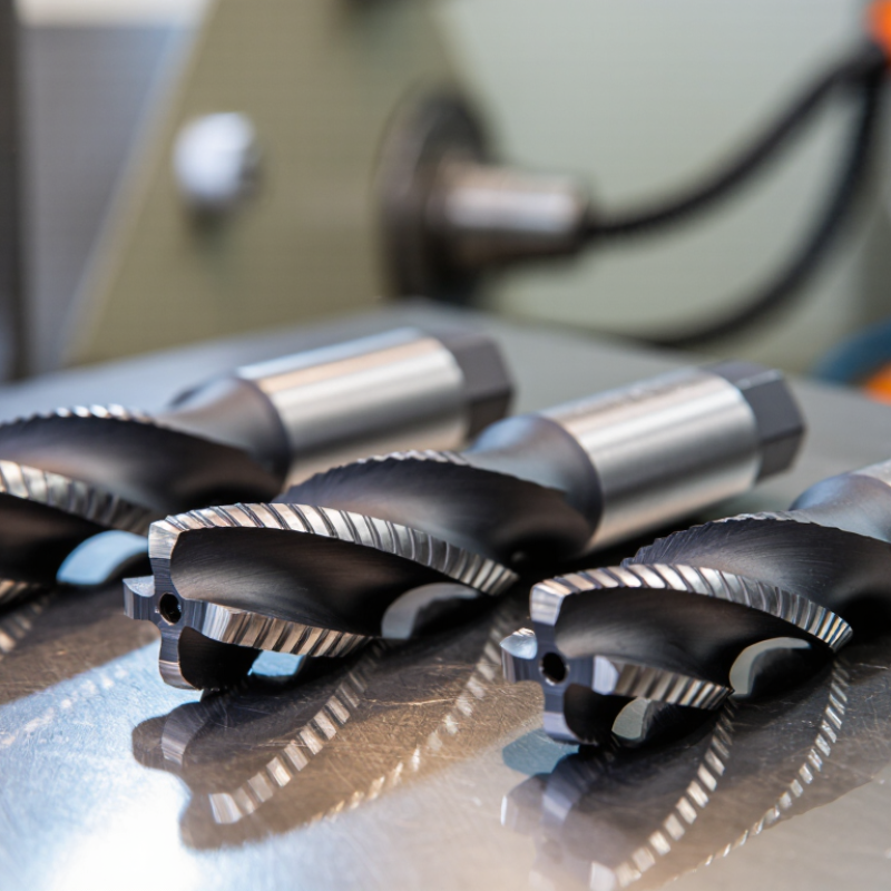
What Are Solid Carbide Chucking Reamers?

Solid Carbide Chucking Reamers: Definition, Purpose, and Applications

Solid carbide chucking reamers are one-piece cutting tools designed to finish existing holes. Their carbide body provides high stiffness, hardness, and wear resistance. Unlike drills, they remove limited material. Their main purpose is accuracy, not hole creation.

These reamers support tight dimensional control in hardened steel, cast iron, aluminum, and composite components. Common applications include hydraulic blocks, automotive parts, aerospace fittings, and precision fixtures. A 2024 MarketsandMarkets report projects the global cutting-tool market to reach about 43 billion dollars by 2029. The report also identifies carbide tooling as a major growth segment. That trend reflects demand for longer tool life and reduced setup time. Still, reports rarely reflect every workshop condition. Real results depend heavily on machine rigidity, coolant, and operator judgment.

Tips: Use the smallest practical stock allowance. Keep the tool aligned. Follow the recommended cutting speed and feed. Check hole size after the first component. A rigid holder matters. Through-coolant can improve chip evacuation in deep holes. However, excessive speed may cause edge chipping. I have found that a slower trial cut often prevents expensive rework. Perfect settings do not exist for every alloy. The ISO 286-2 tolerance system helps define the target hole class before machining begins.

Carbide Grades K10–K20, Flutes, Shanks, and Cutting-Edge Geometry

What Are Solid Carbide Chucking Reamers?

Solid carbide chucking reamers are precision tools for finishing existing holes. They remove a small amount of material and improve size, roundness, and surface quality. Carbide stays rigid at cutting speeds that may challenge high-speed steel. However, rigidity alone does not prevent poor results. A loose setup, damaged holder, or excessive stock can quickly ruin the hole.

Carbide grades K10–K20 offer different balances of hardness and toughness. K10 is harder and suits stable machines, clean materials, and light finishing cuts. K20 tolerates more interrupted cutting and vibration, though it may wear faster in abrasive conditions. K15 can serve as a practical middle choice. Flute design also matters. Straight flutes support controlled finishing in many applications, while helical flutes can improve chip movement. Too many flutes may restrict chip space. Too few can reduce support at the cutting edge.

Tips: Check the hole before reaming. Leave only a small, even allowance. Use a rigid chucking system and steady coolant flow. Match the shank to the holder; a poor fit creates runout. Inspect the cutting-edge geometry, including relief angle, margin width, and edge sharpness. A balanced geometry helps the tool enter smoothly without rubbing. In practice, I would not trust catalog values alone. Machine condition, workpiece hardness, and operator control can change the result. Sometimes a slower feed produces a better finish, even when the recommended data suggests otherwise.

Hole Sizing: H7 Tolerances and the 0.1–0.3 mm Reaming Allowance

Solid carbide chucking reamers produce accurate, smooth holes after drilling or boring. Their rigid carbide construction helps limit deflection during finishing. They are not designed to correct badly misplaced holes. Important distinction. Stable setup matters as much as tool quality.

For an H7 hole, the nominal diameter is only part of the requirement. The H7 tolerance limits change with the nominal hole size. Therefore, select the reamer for the finished diameter, not merely the drill diameter. A practical reaming allowance is often 0.1–0.3 mm on diameter. The exact value depends on material, hole size, and machine stability. Too little stock may cause rubbing or poor sizing. Too much stock can create chatter, heat, and premature wear. The allowance should be confirmed against the tooling plan and component drawing.

Use a rigid holder with minimal overhang and remove chips continuously. Consistent feed and suitable coolant help maintain the cutting edge. Measure the first hole with a calibrated plug gauge or bore gauge. Measure carefully. Runout, thermal growth, and worn reamers can push an H7 hole outside tolerance. A common shop mistake is treating every 0.1–0.3 mm allowance as universal. It is only a starting range. Actual results should be checked on the machine, especially with tough alloys or deep holes. Inspecting both early and later parts can reveal gradual tool wear before the batch drifts.

What Are Solid Carbide Chucking Reamers? - Hole Sizing: H7 Tolerances and the 0.1–0.3 mm Reaming Allowance
Data Dimension Specification or Guideline Practical Meaning Typical Application
Solid Carbide Chucking Reamer Fundamentals
Tool type Solid carbide chucking reamer A rotary finishing tool manufactured from one piece of carbide and held in a machine chuck or toolholder. Accurate finishing of pre-drilled, bored, or cast holes.
Primary function Hole sizing and surface finishing Removes a controlled amount of material to improve hole diameter, roundness, cylindricity, and surface quality. Production machining where repeatable hole size is required.
Tool material Solid cemented carbide Provides high stiffness and wear resistance compared with high-speed steel, but is less tolerant of shock and misalignment. Rigid CNC machines and stable workholding conditions.
Cutting edge arrangement Usually straight or helical flutes Straight flutes are commonly used for stable, interrupted, or shallow cutting conditions; helical flutes generally promote smoother cutting in continuous holes. Selection depends on workpiece material, chip evacuation, and hole geometry.
Cutting allowance Typically 0.1–0.3 mm on diameter The pre-hole should normally be smaller than the finished hole by the selected diameter allowance. The exact value depends on diameter, material, rigidity, and tool design. Use as a starting range, then validate through trial machining and measurement.
Machine condition High rigidity and low runout preferred Excessive spindle runout, vibration, or tool deflection can produce oversize, tapered, or out-of-round holes. Precision drilling, boring, and reaming operations.
ISO H7 Hole Tolerance Reference
Nominal Hole Diameter Range H7 Lower Deviation H7 Upper Deviation Permitted Hole Size Range
3 to 6 mm 0.000 mm +0.012 mm Basic size to basic size + 0.012 mm
Over 6 to 10 mm 0.000 mm +0.015 mm Basic size to basic size + 0.015 mm
Over 10 to 18 mm 0.000 mm +0.018 mm Basic size to basic size + 0.018 mm
Over 18 to 30 mm 0.000 mm +0.021 mm Basic size to basic size + 0.021 mm
Over 30 to 50 mm 0.000 mm +0.025 mm Basic size to basic size + 0.025 mm
Typical Pre-Hole and Reaming Allowance Examples
Finished H7 Hole H7 Size Limits Typical Diameter Allowance Indicative Pre-Hole Size
Ø5 mm H7 5.000–5.012 mm 0.10–0.15 mm Approximately Ø4.85–4.90 mm
Ø8 mm H7 8.000–8.015 mm 0.10–0.15 mm Approximately Ø7.85–7.90 mm
Ø12 mm H7 12.000–12.018 mm 0.15–0.20 mm Approximately Ø11.80–11.85 mm
Ø20 mm H7 20.000–20.021 mm 0.20–0.25 mm Approximately Ø19.75–19.80 mm
Ø30 mm H7 30.000–30.021 mm 0.20–0.30 mm Approximately Ø29.70–29.80 mm
Ø40 mm H7 40.000–40.025 mm 0.25–0.30 mm Approximately Ø39.70–39.75 mm
Process and Inspection Considerations
Reaming direction Normally feed continuously in one direction Stopping or reversing while the cutting edges are engaged can damage the tool and affect hole quality. Through-holes and blind holes with suitable chip evacuation.
Coolant requirement Use coolant or cutting fluid appropriate to the workpiece Lubrication and chip removal help reduce built-up edge, heat, and surface damage. Continuous coolant delivery is preferred where machine setup permits.
Runout control Keep total indicated runout as low as practical Runout directly influences hole oversize, lobing, and uneven tool wear. Precision toolholders and clean, undamaged gauge surfaces.
Measurement method Use a calibrated bore gauge, air gauge, or suitable plug gauge Measure the finished hole after the part has stabilized near inspection temperature. Quality verification against the specified H7 limits.
Allowance adjustment Reduce or increase within the 0.1–0.3 mm starting range as needed Hard materials, interrupted holes, weak setups, and small diameters may require a more conservative allowance. Confirm with cutting trials rather than relying on allowance alone.
Note: H7 values shown are ISO 286 hole-basis tolerance values. Reaming allowances are practical starting guidelines expressed on diameter, not universal rules. Final results depend on workpiece material, pre-hole accuracy, tool geometry, coolant, spindle runout, feed, machine rigidity, and inspection conditions.

Cutting Parameters: Speeds, Feeds, Coolant, and ≤0.01 mm Runout

A solid carbide chucking reamer uses a rigid cutting body to finish an existing hole accurately. Unlike a drill, it removes only a small allowance. The hole must already be straight and properly located. Carbide handles high cutting speeds, but it dislikes vibration, interrupted cuts, and poor alignment.

Cutting speed depends on the workpiece. For a 10 mm reamer in medium carbon steel, 30–60 m/min is a reasonable starting range. That equals roughly 955–1,910 rpm. Begin near the lower value when the machine, fixture, or material is uncertain.

Feed is measured per revolution, not per tooth. A practical starting range may be 0.10–0.25 mm/rev for this diameter. Too little feed can rub the margin. Too much feed can damage the hole.

Use a clean, continuous coolant stream aimed at the cutting edges. Through-tool coolant is helpful for deep holes, but external coolant can work with short engagement. Check runout at the holder and near the reamer’s cutting end. Keep total indicated runout at or below 0.01 mm. Even a small error can create a bell-mouthed hole or uneven wear. I once increased speed before checking alignment. The result was heat, not productivity. That choice was not perfect. Test one hole, measure its size and roundness, then adjust one parameter at a time. Avoid stopping the reamer inside the hole. Withdraw it while rotating, with steady machine control.

Performance Checks: Ra 0.8–1.6 μm Finish, Tool Life, and Inspection

Solid carbide chucking reamers should be judged by measured results, not appearance. For many finishing operations, a practical target is Ra 0.8–1.6 μm. ASME B46.1-2019 defines Ra as the arithmetic mean surface deviation. It does not guarantee functional performance. Hole size, roundness, and entry burrs still matter.

Check the first five holes separately. Record Ra, diameter, cylindricity, and spindle load. A calibrated contact profilometer should use a suitable cutoff length and consistent tracing direction. ISO 21920-2:2021 emphasizes controlled measurement conditions and reporting. Without them, two operators can produce different “results.” That is an uncomfortable weakness in many shop records.

Tool life needs a defined failure limit. For example, stop testing when diameter drift exceeds the drawing tolerance, Ra rises above 1.6 μm, or cutting edges show measurable chipping. ISO 3685 provides a useful tool-life testing framework, although it focuses on single-point turning tools. Adapt it carefully for reaming. Log hole count, coolant condition, material batch, and cutting speed. A tool lasting 300 holes may be excellent in one alloy and poor in another. NIST statistical guidance also supports repeated measurements, not one impressive sample. I would inspect every tenth hole during trials, then increase sampling only after the process proves stable. The first result is often misleading.

What Are Solid Carbide Chucking Reamers?

Performance checks for solid carbide chucking reamers commonly include surface finish, usable tool life, and dimensional inspection. The reference values below represent typical planning ranges for stable production trials and must be verified for the specific workpiece, coolant, machine, and cutting conditions.

A surface finish of Ra 0.8–1.6 μm is a practical target range for many precision reaming applications. Tool life is shown as the approximate number of holes before finish or dimensional results require tool replacement. Final acceptance should be based on measured Ra, hole size, cylindricity, and tool wear rather than tool-life estimates alone.

FAQS

What is a solid carbide chucking reamer?

It is a one-piece cutting tool for finishing existing holes. It removes only a small amount of material. It improves size, roundness, and surface quality. It does not replace a drill.

Which materials can these reamers finish?

They can finish hardened steel, cast iron, aluminum, and composite components. Results vary with hardness and machine rigidity. Material behavior matters.

What are common applications?

Typical uses include hydraulic blocks, automotive parts, aerospace fittings, and precision fixtures. A finished hole may guide a pin or support a fitting. The application decides the tolerance.

How much material should remain before reaming?

Leave the smallest practical, even allowance. Excessive stock increases cutting load and may damage the edge. Too little stock can cause rubbing. Check the first component carefully.

How should the reamer be held?

Use a rigid chucking system with minimal runout. Match the shank to the holder. A poor fit can create a tapered or oversized hole. Alignment is critical.

What is the difference between K10, K15, and K20 carbide grades?

K10 offers higher hardness for stable machines and light finishing cuts. K20 provides more toughness during vibration or interrupted cutting. K15 is a practical middle option. No grade wins everywhere.

Should straight or helical flutes be selected?

Straight flutes support controlled finishing in many applications. Helical flutes can improve chip movement, especially in deeper holes. Too many flutes reduce chip space. Too few may weaken edge support.

How can operators reduce poor hole results?

Check the existing hole before machining. Keep the tool aligned and use steady coolant flow. Through-coolant may help remove chips from deep holes. Start with a cautious trial cut. I would not trust catalog data alone.

Conclusion

Solid Carbide Chucking Reamers are precision cutting tools designed to enlarge and finish pre-drilled holes with excellent accuracy, stability, and surface quality. Made from solid carbide, they are suitable for demanding machining operations involving hard or abrasive materials. Their K10–K20 carbide grades offer different balances of hardness and toughness, while flute design, shank form, and cutting-edge geometry influence chip evacuation, rigidity, and cutting performance. These reamers are commonly used where consistent hole dimensions and reliable repeatability are required.

For H7 hole tolerances, the pre-machined hole should generally leave a reaming allowance of approximately 0.1–0.3 mm, depending on hole size and material. Correct cutting speed, feed rate, and coolant selection help prevent heat buildup, edge damage, and poor finish. Machine and tool setup should also maintain runout at or below 0.01 mm. Performance can be evaluated through dimensional inspection, tool-life monitoring, and surface-finish checks, with a typical target of Ra 0.8–1.6 μm when conditions are properly controlled.

Amelia

Amelia

Amelia is a dedicated marketing professional with extensive expertise in developing clear, engaging, and customer-focused content for a technology-driven company. With a strong understanding of the company’s products, services, and target markets, she translates complex information into practical......